Applicable for models SUN-5K/6K/8K/10K/12K-SG04LP3-EU
5. LCD Display Icons
5.1 Main Screen
The LCD is a touchscreen, below screen shows the overall information about the inverter.
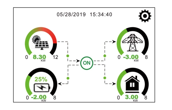
- The icon in the center of the home screen indicates that the system is in Normal operation. If it turns into “comm./F01~F64”, means the inverter has communication errors or other errors, and the error message will display under this icon (F01-F64 errors, detailed error info can be viewed in the System Alarms menu).
- At the top of the screen is the time.
- System Setup Icon, Press this set button, and you can enter into the system setup screen which includes Basic Setup, Battery Setup, Grid Setup, System Work Mode, Generator port use, Advanced function, and Li-Batt info.
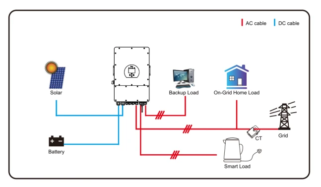
- The main screen shows the info including Solar, Grid, Load, and Battery. It also displays the energy flow direction by an arrow. When the power is approximately high level, the color on the panels will change from green to red so system info shows vividly on the main screen.
- PV power and Load power always keep positive.
- Grid power negative means selling to the grid, and positive means getting from the grid.
- Battery power negative means charge, and positive means discharge.
5.1.1 LCD operation flow chart

5.2 Solar Power Curve


5.3 Curve Page-Solar & Load & Grid


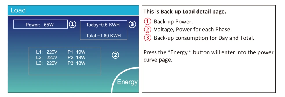
Solar power curve for daily, monthly, yearly and total can be roughly checked on the LCD, for more accuracy power generation, pls check on the monitoring system. Click the up and down arrow to check power curve of different period.


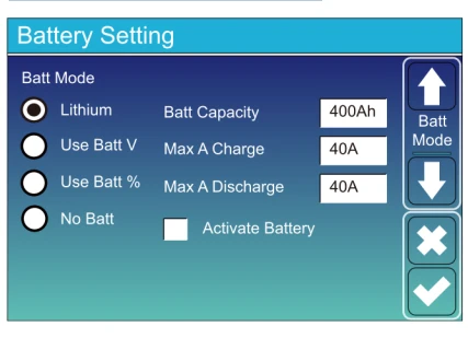
Battery capacity: it tells Deye hybrid inverter to know your battery bank size.
Use Batt V: Use Battery Voltage for all the settings (V).
Use Batt %: Use Battery SOC for all the settings (%).
Max. A charge/discharge: Max battery charge/discharge current (0-120A for 5KW model, 0-150A for 6KW model, 0-190A for 8KW model, 0-210A for 10KW model, 0-240A for 12KW model).
For AGM and Flooded, we recommend Ah battery size x 20% = Charge/Discharge amps.
For Lithium, we recommend Ah battery size x 50% = Charge/Discharge amps.
For Gel, follow manufacturer‘ s instructions.
No Batt: tick this item if no battery is connected to the system.
Active battery: This feature will help recover a battery that is over discharged by slowly charging from the solar array or grid.
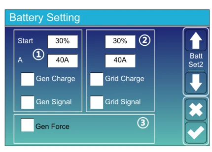
1 and 3. This is Battery Setup page.
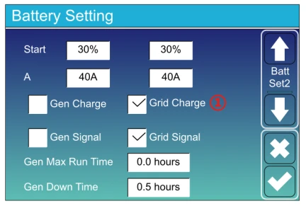
Start =30%: Percent S.O.C at 30% system will AutoStart a connected generator to charge the battery bank.
A = 40A: Charge rate of 40A from the attached generator in Amps.
Gen Charge: uses the gen input ofthe system to charge battery bank from an attached generator.
Gen Signal: Normally open relay that closes when the Gen Start signal state is active.
Gen Force: When the generator is connected, it is forced to start the generator without meeting other conditions.
2. This is Grid Charge, you need select
Start =30%: No use, Just for customization.
A = 40A: It indicates the Current that the Grid charges the Battery.
Grid Charge: It indicates that the grid charges the battery.
Grid Signal: Disable.
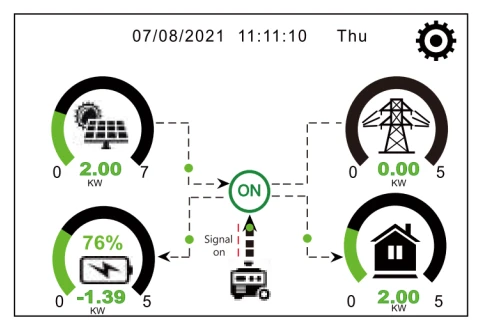
This page tells the PV and diesel generator power the load and battery.
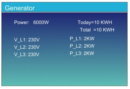
This page tells generator output voltage, frequency, power. And, how much energy is used from generator.
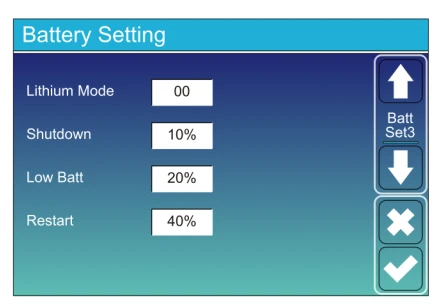
Lithium Mode: This is BMS protocol. Please reference the document (Approved Battery).
Shutdown 10%: It indicates the inverter will shutdown if the SOC is below this value.
Low Batt 20%: It indicates the inverter will alarm if the SOC is below this value.
Restart 40%: Battery voltage at 40% AC output will resume.
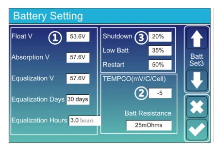
- There are 3 stages of charging the Battery.
- This is for professional installers, you can keep it if you do not know.
- Shutdown 20%: The inverter will shutdown if the SOC is below this value.
Low Batt 35%: The inverter will alarm if the SOC is below this value.
Restart 50%: Battery SOC at 50% AC output will resume.
| Battery Type | Absorption Stage | Float Stage | Torque value (every 30 day 3hr) |
|---|---|---|---|
| AGM (or PCC) | 14.2v (57.6v) | 13.4v (53.6v) | 14.2v (57.6v) |
| Gel | 14.1v (56.4v) | 13.5v (54.0v) | |
| Wet | 14.7v (59.0v) | 13.7v (55.0v) | 14.7v (59.0v) |
| Lithium | Follow its BMS voltage parameters | ||
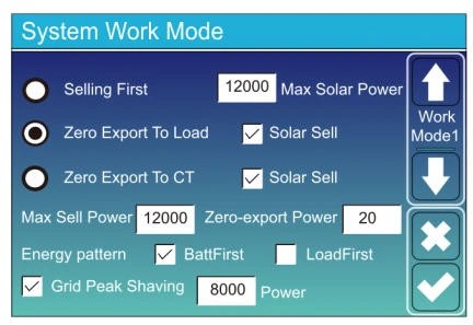
Work Mode
Selling First: This Mode allows the hybrid inverters to sell back any excess power produced by the solar panels to the grid. If the time of use is active, the battery energy also can be sold into the grid.
The PV energy will be used to power the load and charge the battery and then excess energy will flow to the grid.
Power source priority for the load is as follows:
- Solar Panels.
- Grid.
- Batteries (until programable % discharge is reached).
Zero Export To Load: The hybrid inverter will only provide power to the backup load connected. The hybrid inverter will neither provide power to the home load nor sell power to the grid. The built-in CT will detect power flowing back to the grid and will reduce the power of the inverter only to supply the local load and charge the battery.

Zero Export To CT: Hybrid inverter will not only provide power to the backup load connected but also give
power to the home load connected. If PV power and battery power are insufficient, it will take grid energy
as a supplement. The hybrid inverter will not sell power to the grid. In this mode, a CT is needed. For the installation method of the CT please refer to chapter 3.6 CT Connection. The external CT will detect power flowing back to the grid and will reduce the power of the inverter only to supply the local load, and charge the battery and home load.

Solar Sell: “Solar sell” is for Zero export to load or Zero export to CT: when this item is active, the surplus energy can be sold back to the grid. When it is active, PV Power source priority usage is as follows: load consumption and charge the battery and feed into the grid.
Max. sell power: Allowed the maximum output power to flow to the grid.
Zero-export Power: for zero-export mode, it tells the grid output power. Recommend setting it as 20-100W to ensure the hybrid inverter won‘t feed power to the grid.
Energy Pattern: PV Power source priority.
Batt First: PV power is firstly used to charge the battery and then used to power the load. If PV power is insufficient, the grid will make a supplement battery and load simultaneously.
Load First: PV power is firstly used to power the load and then used to charge the battery. If PV power is insufficient, Grid will provide power to load.
Max Solar Power: allowed the maximum DC input power.
Grid Peak-shaving: when it is active, the grid output power will be limited within the set value. If the load power exceeds the allowed value, it will take PV energy and a battery as a supplement. If still can’t meet the load requirement, grid power will increase to meet the load needs.
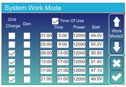
Time of use: it is used to program when to use a grid or generator to charge the battery, and when to discharge the battery to power the load. Only tick “Time Of Use” and then the following items (Grid, charge, time, power, etc.) will take effect.
Note: when in selling the first mode and clicking time of use, the battery power can be sold into the grid.
Grid charge: utilize the grid to charge the battery in a time period.
Gen charge: utilize a diesel generator to charge the battery in a time period.
Time: real-time, range of 01:00-24:00.
Note: when the grid is present, only the “time of use” is ticked, then the battery will discharge. Otherwise, the battery won’t discharge even if the battery SOC is full. But in the off-grid mode (when the grid is not available, the inverter will work in the off-grid mode automatically).
Power: Max. discharge power of battery allowed.
Batt (V or SOC %): battery SOC % or voltage at when the action is to happen.
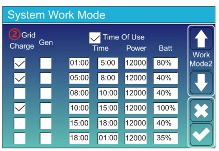
For example
During 01:00-05:00,
if the battery SOC is lower than 80%, it will use the grid to charge the battery until the battery SOC reaches 80%.
During 05:00-08:00,
if the battery SOC is higher than 40%, the hybrid inverter will discharge the battery until the SOC reaches 40%. At the same time, if the battery SOC is lower than 40%, then the grid will charge the battery SOC to 40%.
During 08:00-10:00,
if the battery SOC is higher than 40%, the hybrid inverter will discharge the battery until the SOC reaches 40%.
During 10:00-15:00,
when the battery SOC is higher than 80%, the hybrid inverter will discharge the battery until the SOC reaches 80%.
During 15:00-18:00,
when the battery SOC is higher than 40%, the hybrid inverter will discharge
the battery until the SOC reaches 40%.
During 18:00-01:00,
when battery SOC is higher than 35%, the hybrid inverter will discharge
the battery until the SOC reaches 35%.
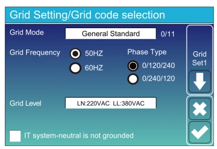
Grid Mode: General Standard, UL1741 & IEEE1547, CPUC RULE21, SRD-UL-1741, CEI 0-21, Australia A, Australia B, Australia C, EN50549_CZ-PPDS(>16A),
New Zealand, VDE4105, OVE-Directive R25.
Please follow the local grid code and then choose the corresponding grid standard.
Grid level: there’re several voltage levels for the inverter output voltage when it is in off-grid mode.
LN:230VAC LL:400VAC, LN:240VAC LL:420VAC, LN:120VAC LL:208VAC, LN:133VAC LL:23OVAC.
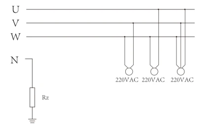
IT system: For the IT grid system, the Line voltage (between any two lines in a three-phase circuit) is 230Vac, and the diagram is as follows. If your grid system is an IT system, please enable “IT system” and tick the “Grid level” as 133-3P as the below picture shows.
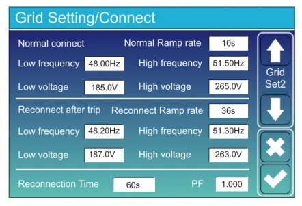
Normal connect: The allowed grid voltage/frequency range when the inverter first time connects to the grid.
Normal Ramp rate: It is the startup power ramp.
Reconnect after the trip: The allowed grid voltage /frequency range for the
the inverter connects the grid after the inverter trip from the grid.
Reconnect Ramp rate: It is the reconnection power ramp.
Reconnection time: The waiting time period for the inverter to connect the grid again.
PF: Power factor which is used to adjust inverter reactive power.
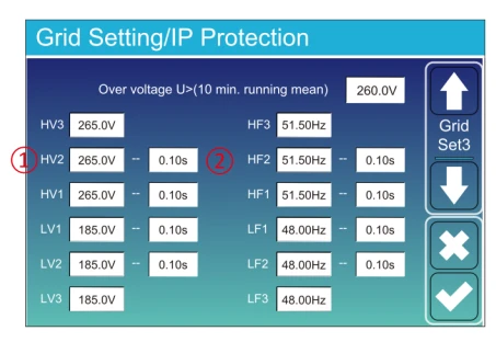
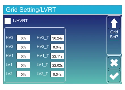
HV1: Level 1 overvoltage protection point;
(1)HV2: Level 2 overvoltage protection point; (2)0.10s—Trip time.
HV3: Level 3 overvoltage protection point.
LV1: Level 1 undervoltage protection point;
LV2: Level 2 undervoltage protection point;
LV3: Level 3 undervoltage protection point.
HF1: Level 1 over frequency protection point;
HF2: Level 2 over frequency protection point;
HF3: Level 3 over frequency protection point.
LF1: Level 1 under frequency protection point;
LF2: Level 2 under frequency protection point;
LF3: Level 3 under frequency protection point.
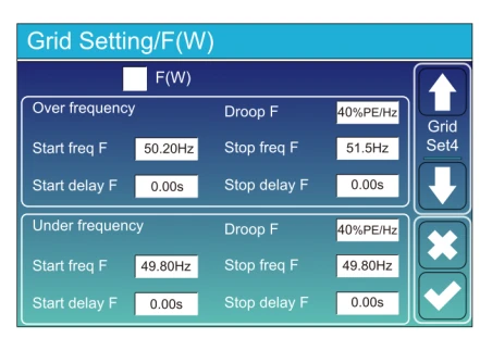
FW: this series inverter is able to adjust inverter output power according to grid frequency.
Droop F: percentage of nominal power per Hz
For example, “Start freq F>50.2Hz, Stop freq F<51.5, Droop F=40%PE/Hz” when the grid frequency reaches 50.2Hz, the inverter will decrease its active power at Droop F of 40%. And then when the grid system frequency is less than 50.1Hz, the inverter will stop decreasing output power.
For the detailed setup values, please follow the local grid code.
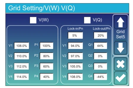
Lock-in/Pn 5%: When the inverter active power is less than 5% rated power, the VQ mode will not take effect.
Lock-out/Pn 20%: If the inverter active power is increasing from 5% to 20% rated power, the VQ mode will take effect again.
For example: V2=110%, P2=80%. When the grid voltage reaches 110% times of rated grid voltage, the inverter output power will reduce its active output power to 80% rated power.
For example: V1=94%, Q1=44%. When the grid voltage reaches 94% times of rated grid voltage, the inverter output power will output 44% reactive output power.
For the detailed setup values, please follow the local grid code.
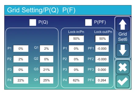
P(Q): It is used to adjust the inverter reactive power according to the set active power.
P(PF): It is used to adjust the inverter PF according to the set active power.
For the detailed setup values, please follow the local grid code.
Lock-in/Pn 50%: When the inverter output active power is less than 50% rated power, it won’t enter the P(PF) mode.
Lock-out/Pn 50%: When the inverter output active power is higher than 50% rated power, it will enter the P(PF) mode.
Note: only when the grid voltage is equal to or higher than 1.05 times of rated grid voltage, then the P(PF) mode will take effect.
Reserved: This function is reserved. lt is not
recommended.
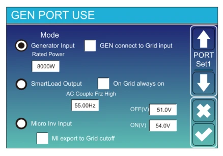
Generator input rated power: allowed Max. power from a diesel generator.
GEN connect to grid input: connect the diesel generator to the grid input port.
Smart Load Output: This mode utilizes the Gen input connection as an output which only receives power when the battery SOC is above a user-programmable threshold.
e.g. ON: 100%, OFF=95%: When the battery bank SOC reaches 100%, Smart Load Port will switch on automatically and power the load connected. When the battery bank SOC < 95%, the Smart Load Port will switch off automatically.
Smart Load OFF Batt
• Battery SOC at which the Smart load will switch off.
Smart Load ON Batt
• Battery SOC at which the Smart load will switch on. simultaneously and then the Smart load will switch on.
On Grid always on: When click “on Grid always on” the smart load will switch on when the grid is present.
Micro lnv Input: To use the Generator input port as a micro-inverter on grid inverter input (AC coupled), this feature will also work with “Grid-Tied” inverters.
* Micro lnv Input OFF: when the battery SOC exceeds setting value, Microinveter or grid-tied inverter will shut down.
* Micro lnv Input ON: when the battery SOC is lower than setting value, Microinveter or grid-tied inverter will start to work.
AC Couple Frz High: If choosing”Micro lnv input”, as the battery SOC reaches gradually setting value (OFF), During the process, the microinverter output power will decrease linear. When the battery SOC equals to the setting value (OFF), the system frequency will become the setting value (AC couple Frz high) and the Microinverter will stop working.
Ml export to grid cutsoff: Stop exporting power produced by the microinverter to the grid.
* Note: Micro lnv Input OFF and On is valid for some certain FW version only.

Solar Arc Fault ON: This is only for US.
System selfcheck: Disabled. This is only for factory.
Gen Peak-shaving: Enable When the power of the generator exceeds the rated value of it, the inverter will provide the redundant part to ensure that the generator will not overload.
DRM: For AS4777 standard.
Backup Delay: Reserved.
BMS_Err_Stop: When it is active, if the battery BMS failed to communicate with inverter, the inverter will stop working and report fault.
Signal island mode: If “Signal island mode” is checked and When inverter is in off-grid mode, the relay on the Neutral line (load port N line) will switch ON then the N line (load port N line) will bind to inverter ground.

Asymmetric phase feeding: If it was checked, the excess PV energy that feeds into the grid will be balanced on the three phase.

Ex_Meter For CT: when using zero-export to CT mode, the hybrid inverter can select EX_Meter For CT function and use the different meters e.g. CHNT and Eastron.

This page show Inverter ID, Inverter version and alarm codes.
HMI: LCD version
MAIN: Control board FW version