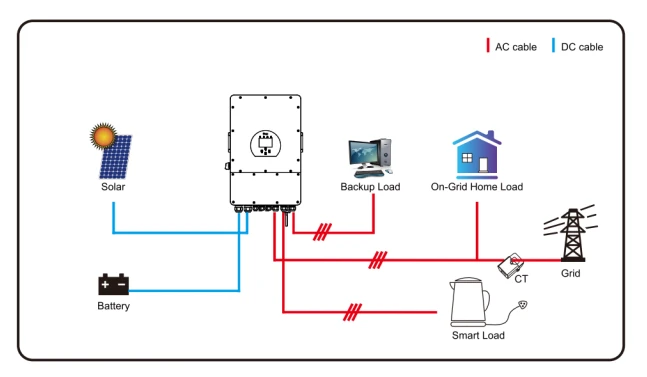
Applicable for models SUN-5K/6K/8K/10K/12K-SG04LP3-EU
6. Mode


7. Limitation of Liability
In addition to the product warranty described above, the state and local laws and regulations provide financial compensation for the product’s power connection (including violation of implied terms and warranties). The company hereby declares that the terms and conditions of the product and the policy cannot and can only legally exclude all liability within a limited scope.
Chart 7-1 Fault information| Error code | Description | Solutions |
|---|---|---|
| F01 | DC input polarity reverse fault | 1. Check the PV input polarity 2. Seek help from us, ifcan not go back to normal state. |
| F07 | DC_START_Failure | 1. The BUS voltage can’t be built from PV or battery. 2. Restart the inverter, If the fault still exists, please contact us for help |
| F13 | working mode change | 1. When the grid type and frequency changed it will report F1 2. When the battery mode was changed to “No battery” mode,it will report F13; 3. For some old FW version, it will report F13 when the system work mode changed; 4, Generally, it will disappear automatically when shows F13; 5. If still same, and turn off the DC switch and AC switch and wait for one minute and then turn on the DC/AC switch; 6. Seek help from us, if can not go back to normal state. |
| F15 | AC over current fault of software | AC side over current fault 1. Please check whether the backup load power and common load power are within the range; 2. Restart and check whether it is in normal; 3. Seek help from us, ifcan not go back to normal state. |
| F16 | AC leakage current fault | Leakage current fault 1. Check the PV side cable ground connection 2. Restart the system 2-3 times 3. if the fault still existing, please contact us for help |
| F18 | AC leakage current fault | Leakage current fault 1. Check the PV side cable ground connection 2. Restart the system 2-3 times 3. if the fault still existing, please contact us for help. |
| F20 | DC over current fault of the hardware | DC side over current fault 1. Check PV module connect and battery connect; 2. When in the off—grid mode, the inverter startup with big power load, it may report F20. Please reduce the load power connected; 3. Turn off the DC switch and AC switch and then wait one minute, then turn on the DC/AC switch again; 4. Seek help from us, if can not go back to normal state. |
| F21 | Tz_HV_Overcurr_fault | BUS over current. 1. Check the PV input current and battery current setting 2. Restart the system 2~3 times. 3. If the fault still exists, please contact us for help. |
| F22 | Tz_EmergStop_Fault | Remotely shutdown 1. it tells the inverter is remotely controlled. |
| F23 | Tz_GFCI_OC_ current is transient over current | Leakage current fault 1. Check PV side cable ground connection. 2. Restart the system 2~3 times. 3. If the fault still exists, please contact us for help. |
| F24 | DC insulation failure | PV isolation resistance is too low 1. Check the connection of PV panels and inverter is firmly and correctly; 2. Check whether the PE cable ofinverter is connected to ground; 3. Seek help from us, if can not go back to normal state. |
| F26 | The DC busbar is unbalanced | 1. Please wait for a while and check whether it is normal; 2. When the load power of 3 phases is big different, it will report the F26. 3. When there’s DC leakage current, it will report F26 4. Restart the system 2~3 times. 5. Seek help from us, if can not go back to normal state. |
| F29 | Parallel CAN Bus fault | 1. When in parallel mode, check the parallel communication cable connection and hybrid inverter communication address setting; 2. During the parallel system startup period, inverters will report F29. But when all inverters are in ON status, it will disappear automatically; 3. lf the fault still exists, please contact us for help. |
| F34 | AC Overcurrent fault | 1. Check the backup load connected, make sure it is in allowed power range. 2. If the fault still exists, please contact us for help. |
| F41 | Parallel system stop | 1. Check the hybrid inverter work status. If there is lpcs hybrid inverter shutdown, all hybrid inverters will report F41 fault. 2. lf the fault still exists, please contact us for help. |
| F42 | AC line low voltage | Grid voltage fault 1. Check the AC voltage is in the range of standard voltage inspecification; 2. Check whether grid AC cables are firmly and correctly connected; 3. Seek help from us, ifcan not go back to normal state. |
| F46 | backup battery fault | 1. Please check each battery status, such as voltage/ SOC and parameters etc., and make sure all the parameters are same. 2. If the fault still exists, please contact us for help. |
| F47 | AC over frequency | Grid frequency out ofrange 1. Check the frequency is in the range of specification or not; 2. Check whether AC cables are firmly and correctly connected; 3. Seek help from us, ifcan not go back to normal state. |
| F48 | AC lower frequency | Grid frequency out ofrange 1. Check the frequency is in the range of specification or not; 2. Check whether AC cables are firmly and correctly connected; 3. Seek help from us, if can not go back to normal state. |
| F55 | DC busbar voltage is too high | BUS voltage is too high 1. Check whether battery voltage is too high; 2. Check the PV input voltage, make sure it is within the allowed range; 3. Seek help from us, if can not go back to normal state. |
| F56 | DC busbar voltage is too low | Battery voltage low 1. Check whether battery voltage is too low; 2. If the battery voltage is too low, using PV or grid to charge thebattery; 3. Seek help from us, if can not go back to normal state. |
| F58 | BMS communication fault | 1. it tells the communication between the hybrid inverter and battery BMS disconnected when “BMS_Err-Stop” is active” 2, if don’t want to see this happen, you can disable “BMS_Err-Stop” item on the LCD. 3. lf the fault still exists, please contact us for help. |
| F62 | DRMs0_stop | 1. the DRM function is for Australia market only. 2. Check the DRM function is active or not 3. Seek help from us, if can not go back to normal state after restart the system. |
| F63 | ARC fault | 1. ARC fault detection is only for US market; 2. Check PV module cable connection and clear the fault; 3. Seek help from us, if can not go back to normal state. |
| F64 | Heat sink high temerature failure | The heat sink temperature is too high 1. Check whether the work environment temperature is too high; 2. Turn off the inverter for 10mins and restart it; 3. Seek help from us, if can not go back to a normal state. |
Under the guidance of our company, customers return our products so that our company can provide service of maintenance or replacement of products of the same value. Customers need to pay the necessary freight and other related costs. Any replacement or repair of the product will cover the remaining warranty period of the product. If any part of the product or product is replaced by the company itself during the warranty period, all rights and interests of the replacement product or component belong to the company.
The factory warranty does not include damage due to the following reasons:
– Damage during transportation of equipment;
– Damage caused by incorrect installation or commissioning;
– Damage caused by failure to comply with operation instructions, installation instructions or maintenance instructions;
– Damage caused by attempts to modify, alter or repair products;
– Damage caused by incorrect use or operation;
– Damage caused by insufficient ventilation of equipment;
– Damage caused by failure to comply with applicable safety standards or regulations;
– Damage caused by natural disasters or force majeure (e.g. floods, lightning, overvoltage, storms, fires, etc.)
In addition, normal wear or any other failure will not affect the basic operation of the product.
Any external scratches, stains, or natural mechanical wear does not represent a defect in the product.
8. Datasheets
- Three Phase Hybrid Inverter DEYE SUN-5K-SG04LP3-EU 5kVA
- Three Phase Hybrid Inverter DEYE SUN-6K-SG04LP3-EU 6kVA
- Three Phase Hybrid Inverter DEYE SUN-8K-SG04LP3-EU 8kVA
- Three Phase Hybrid Inverter DEYE SUN-10K-SG04LP3-EU 10kVA
- Three Phase Hybrid Inverter DEYE SUN-12K-SG04LP3-EU 12kVA
9. Appendix I
Definition of R145 Port Pin for BMS
| No. | RS485 Pin |
|---|---|
| 1 | 485_B |
| 2 | 485_A |
| 3 | — |
| 4 | CAN-H |
| 5 | CAN-L |
| 6 | GND_485 |
| 7 | 485_A |
| 8 | 485_B |

Definition of RJ45 Port Pin for Meter-485
| No. | Meter-485 Pin |
|---|---|
| 1 | METER-485_B |
| 2 | METER-485_A |
| 3 | COM-GND |
| 4 | — |
| 5 | — |
| 6 | COM-GND |
| 7 | METER-485_A |
| 8 | METER-485_B |

Definition of RJ45 Port Pin of “Modbus port” for remote monitoring
| No. | Modbus port |
|---|---|
| 1 | 485_B |
| 2 | 485_A |
| 3 | GND_485 |
| 4 | — |
| 5 | — |
| 6 | GND_485 |
| 7 | 485_A |
| 8 | 485_B |

RS232 port is used to connect the wifi datalogger
| No. | WIFI/RS232 |
|---|---|
| 1 | |
| 2 | TX |
| 3 | RX |
| 4 | |
| 5 | D-GND |
| 6 | |
| 7 | |
| 8 | |
| 9 | 12Vdc |

10. Appendix ll
1. Split Core Current Transformer (CT) dimension: (mm)
2. Secondary output cable length is 4m.

