Fits air manifold models from our catalog SF2-VC, SF3-VC, SF4-VC, SF5-VC.
You can always contact the experts at ToplaKuća to install solar air collectors.
Installation of a roof-mounted collector with ventilated operation mode
The air solar collector of ventilation type provides air intake from the environment, heating and automatic forced supply of warm dry air inside the house (building). The collector mechanism is equipped with a distribution housing with a built-in fan and a solar panel, which ensures the fan operates from solar energy without additional connection to the power grid. The ToplaKuća solar air collector is an efficient energy-saving device.
The roof-mounted ventilation collector is supplied in three packages – housing + installation kit + roof mount.
Recommendations for the location of the collector
The efficiency of the solar collector will depend mainly on its proper location. When selecting the location, the possibility of shade falling on the selected area should be taken into account. The collector should be installed on the south, southeast or southwest side of the building.
It should be taken into account that if the collector is placed on the southeast or southwest side, its efficiency will decrease by 10-15%.
Exhaust unit
In buildings with a low level of thermal insulation, installation of an exhaust unit is not mandatory – the natural gaps in the building will be used as exhaust openings. In buildings with good thermal insulation, it is recommended to install an exhaust unit (optional) for collectors with a ventilation mode of operation.
The exhaust unit is designed to remove cold air from the room and to ensure proper passage of warm air through the building.
The exhaust unit should be installed in the lower part of the building on the side opposite to the collector location. The additional solar panel should be located on the sunny side of the building.


Mounting of exhaust unit (optional)
- Mark and drill the hole in the exhaust unit.
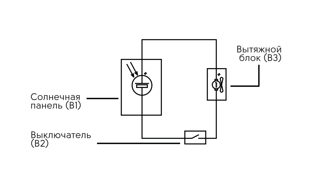
Recommended diameter – 133-140 mm; - On the illuminated south (southeast/southwest) side of the building, attach the additional solar panel (B1) to the self-tapping screws (B6);
- Assemble the exhaust unit. To do this, attach the corrugated pipe (B7) to the return valve with fan (B3), the fan must be located on the side of the house;
- Mount the unit in the mounting hole, seal the hole with mounting foam (not included);
- Connect the fan wires (BZ) to the wire from the optional solar panel (B1) through the switch (B2) according to the diagram below, observing polarity;
- Install the diffuser (B4) on self-tapping screws (B6) from inside the room and the decorative grille (B5) from outside on self-tapping screws (B6).

Assembling the brackets
Determine the required collector tilt angle. The collector should be inclined relative to the vertical by 5-20 degrees.

The diagrams below show possible bracket assemblies for mounting the collector at different angles relative to the roof pitch: 15°, 30°, 45°, 60°, 60°, 75°, 90°, 110°, 135°. Assemble the brackets according to a suitable scheme. To assemble the brackets, connect the holes on the respective parts using bolts R4.7, R4.8 and nuts R4.9.


Attach part R4.6 using bolts R4.7, washers R4.8 and nuts R4.9. For SF4-VC and SF5-VC collectors use additional part R4.5.
It is recommended to install the edge brackets at a distance of 10 cm from the edge of the collector, and the third bracket (for SF4-VC and SF5-VC models) should be installed between the edge brackets at the same distance from them.
The bracket is attached to the roof by the base (part R 4.1).


Installation of a ventilated collector on the roof
- Determine the optimal collector location according to the recommendations above;
- Assemble the bracket with the desired tilt angle;
- Mark the brackets and the mounting hole in the roof. Make sure that the hole does not hit the supporting beams of the building;
- Drill the mounting hole with a drill bit. The recommended diameter of the mounting hole for the duct and control wire is 133-140 mm;
- Install the assembled brackets.
- Pre-assemble the collector:
» remove the protective film from both holes;
» install the filter mounts (V1, V2) on the collector body using screws (C4). The mountings can be installed both parallel and perpendicular to the collector body, according to the convenience of the subsequent filter replacement;
» install the filter (V3) into the mountings (V1, V2);
- install the cut-in with fan and locking spring (V4) using the screws (V6), connecting the wires beforehand, observing the polarity;
» install the thermal insulation gasket (V5) on the tapping;
» attach the insulated corrugated pipe (R2) to the mortise (V4), securely fasten the pipe with a tie (RZ). - Assemble the manifold by attaching it to the brackets as shown in the diagram;
- Route the control wire from the manifold into the mounting hole;
- Install the double-sided roof tapping (R1) by first attaching the corrugated pipe (R2) to the bottom with a tie (RZ). If necessary, cut off excess corrugated pipe. Seal the roof inlet;
- Attach the insulated corrugated pipe to the top of the double-sided tapping (R1). Securely fix the pipe with a pipe tie (RZ);
- On the inside of the building, install a switch (V9) in a convenient location and connect the control wire to it;
- Remove the diffuser mounting part with the non-return valve (V8) and install it with self-tapping screws (V12), having previously attached the corrugated pipe (V7), if necessary cut off excess corrugated pipe;
- Install the diffuser with a check valve (V8) in the mounting part.